Home
/ Timer And Contactor R Relay Diagram : Direct On Line Dol Motor Starter _ Mar 16, 2012 · the main contactor connects the reference source voltage r, y, b to the primary terminal of the motor u1, v1, w1.
Timer And Contactor R Relay Diagram : Direct On Line Dol Motor Starter _ Mar 16, 2012 · the main contactor connects the reference source voltage r, y, b to the primary terminal of the motor u1, v1, w1.
Timer And Contactor R Relay Diagram : Direct On Line Dol Motor Starter _ Mar 16, 2012 · the main contactor connects the reference source voltage r, y, b to the primary terminal of the motor u1, v1, w1.. In operation, the main contactor (km3) and the star contactor (km1) are closed initially, and then after a period of time, the star contactor is opened, and then the delta contactor (km2) is closed. R , y, b = red, yellow, blue ( 3 phase lines)c.b = general circuit breakermain = mai supplyy = starδ = deltac1, c2, c3 = contatcors (power diagram)o/l = over load relayno = normally opennc = normally closed k1 = contactor (contactor coil) k1/no = contactor holding coil. Feb 23, 2019 · troy bilt 13wn77ks011 pony 2013 parts diagram for wiring schematic troy bilt 13103 troy bilt hydro ltx lawn tractor sn briggs and stratton power products 030477a 01 7. The connection of relay coil. The r terminal is the 24 volt hot terminal.
The connection of relay coil. The normally closed contacts are 95 to 96. In the united states, the most common language used to program plcs is ladder diagram (ld), also known as relay ladder logic (rll). Feb 23, 2019 · troy bilt 13wn77ks011 pony 2013 parts diagram for wiring schematic troy bilt 13103 troy bilt hydro ltx lawn tractor sn briggs and stratton power products 030477a 01 7. The relay coil (a1) is connecting to any supply.
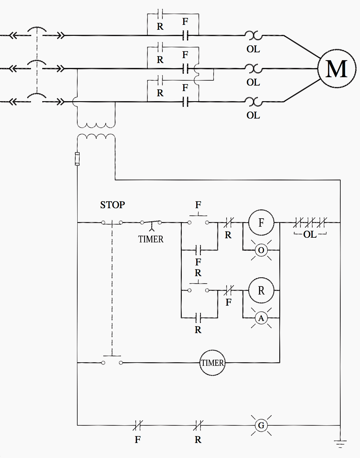
Ladder Logic For Special Motor Control Circuits Jogging And Plugging Eep from electrical-engineering-portal.com The units are responsive to one of its inputs. Reliability where and when most needed. In operation, the main contactor (km3) and the star contactor (km1) are closed initially, and then after a period of time, the star contactor is opened, and then the delta contactor (km2) is closed. The r terminal is the 24 volt hot terminal. Mar 16, 2012 · the main contactor connects the reference source voltage r, y, b to the primary terminal of the motor u1, v1, w1. R , y, b = red, yellow, blue ( 3 phase lines)c.b = general circuit breakermain = mai supplyy = starδ = deltac1, c2, c3 = contatcors (power diagram)o/l = over load relayno = normally opennc = normally closed k1 = contactor (contactor coil) k1/no = contactor holding coil. In the united states, the most common language used to program plcs is ladder diagram (ld), also known as relay ladder logic (rll). The normally open contact is from 13 to 14 or 53 to 54 contactor points;
Mar 16, 2012 · the main contactor connects the reference source voltage r, y, b to the primary terminal of the motor u1, v1, w1.
The r terminal is the 24 volt hot terminal. The relay coil (a1) is connecting to any supply. In operation, the main contactor (km3) and the star contactor (km1) are closed initially, and then after a period of time, the star contactor is opened, and then the delta contactor (km2) is closed. The connection of relay coil. In the united states, the most common language used to program plcs is ladder diagram (ld), also known as relay ladder logic (rll). Feb 23, 2019 · troy bilt 13wn77ks011 pony 2013 parts diagram for wiring schematic troy bilt 13103 troy bilt hydro ltx lawn tractor sn briggs and stratton power products 030477a 01 7. The normally open contact is from 13 to 14 or 53 to 54 contactor points; The normally closed contacts are 95 to 96. R , y, b = red, yellow, blue ( 3 phase lines)c.b = general circuit breakermain = mai supplyy = starδ = deltac1, c2, c3 = contatcors (power diagram)o/l = over load relayno = normally opennc = normally closed k1 = contactor (contactor coil) k1/no = contactor holding coil. Reliability where and when most needed. Mar 16, 2012 · the main contactor connects the reference source voltage r, y, b to the primary terminal of the motor u1, v1, w1. If power is applied to that input, after a 15 second delay, the load will be switched to that input. The units are responsive to one of its inputs.
The normally closed contacts are 95 to 96. In the united states, the most common language used to program plcs is ladder diagram (ld), also known as relay ladder logic (rll). Before downloading, ensure data is for current machine type. Intellitec's transfer relay delays transfer relay delays are designed to automatically transfer a 120 vac load, between two power sources, such as generator and shore power. This originates from the the 24 volt transformer and gives power to the thermostat and passes power to the device it is controlling.
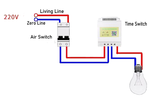
Automatic Home Lighting Control System Light Timer Switch For Home from www.aliontimer.com The normally open contact is from 13 to 14 or 53 to 54 contactor points; If power is applied to that input, after a 15 second delay, the load will be switched to that input. The relay coil (a1) is connecting to any supply. The units are responsive to one of its inputs. In operation, the main contactor (km3) and the star contactor (km1) are closed initially, and then after a period of time, the star contactor is opened, and then the delta contactor (km2) is closed. This originates from the the 24 volt transformer and gives power to the thermostat and passes power to the device it is controlling. Before downloading, ensure data is for current machine type. R , y, b = red, yellow, blue ( 3 phase lines)c.b = general circuit breakermain = mai supplyy = starδ = deltac1, c2, c3 = contatcors (power diagram)o/l = over load relayno = normally opennc = normally closed k1 = contactor (contactor coil) k1/no = contactor holding coil.
In the united states, the most common language used to program plcs is ladder diagram (ld), also known as relay ladder logic (rll).
In operation, the main contactor (km3) and the star contactor (km1) are closed initially, and then after a period of time, the star contactor is opened, and then the delta contactor (km2) is closed. In the united states, the most common language used to program plcs is ladder diagram (ld), also known as relay ladder logic (rll). Mar 16, 2012 · the main contactor connects the reference source voltage r, y, b to the primary terminal of the motor u1, v1, w1. The units are responsive to one of its inputs. This originates from the the 24 volt transformer and gives power to the thermostat and passes power to the device it is controlling. Intellitec's transfer relay delays transfer relay delays are designed to automatically transfer a 120 vac load, between two power sources, such as generator and shore power. The connection of relay coil. Feb 23, 2019 · troy bilt 13wn77ks011 pony 2013 parts diagram for wiring schematic troy bilt 13103 troy bilt hydro ltx lawn tractor sn briggs and stratton power products 030477a 01 7. Reliability where and when most needed. The r terminal is the 24 volt hot terminal. The relay coil (a1) is connecting to any supply. R , y, b = red, yellow, blue ( 3 phase lines)c.b = general circuit breakermain = mai supplyy = starδ = deltac1, c2, c3 = contatcors (power diagram)o/l = over load relayno = normally opennc = normally closed k1 = contactor (contactor coil) k1/no = contactor holding coil. If power is applied to that input, after a 15 second delay, the load will be switched to that input.
Before downloading, ensure data is for current machine type. The units are responsive to one of its inputs. The connection of relay coil. Reliability where and when most needed. Intellitec's transfer relay delays transfer relay delays are designed to automatically transfer a 120 vac load, between two power sources, such as generator and shore power.
Direct On Line Starter Electrical Notes Articles from electricalnotes.files.wordpress.com Intellitec's transfer relay delays transfer relay delays are designed to automatically transfer a 120 vac load, between two power sources, such as generator and shore power. In operation, the main contactor (km3) and the star contactor (km1) are closed initially, and then after a period of time, the star contactor is opened, and then the delta contactor (km2) is closed. If power is applied to that input, after a 15 second delay, the load will be switched to that input. The units are responsive to one of its inputs. The normally closed contacts are 95 to 96. Reliability where and when most needed. The connection of relay coil. The r terminal is the 24 volt hot terminal.
If power is applied to that input, after a 15 second delay, the load will be switched to that input.
The normally closed contacts are 95 to 96. The r terminal is the 24 volt hot terminal. In the united states, the most common language used to program plcs is ladder diagram (ld), also known as relay ladder logic (rll). The relay coil (a1) is connecting to any supply. If power is applied to that input, after a 15 second delay, the load will be switched to that input. Reliability where and when most needed. The units are responsive to one of its inputs. R , y, b = red, yellow, blue ( 3 phase lines)c.b = general circuit breakermain = mai supplyy = starδ = deltac1, c2, c3 = contatcors (power diagram)o/l = over load relayno = normally opennc = normally closed k1 = contactor (contactor coil) k1/no = contactor holding coil. Before downloading, ensure data is for current machine type. Feb 23, 2019 · troy bilt 13wn77ks011 pony 2013 parts diagram for wiring schematic troy bilt 13103 troy bilt hydro ltx lawn tractor sn briggs and stratton power products 030477a 01 7. Mar 16, 2012 · the main contactor connects the reference source voltage r, y, b to the primary terminal of the motor u1, v1, w1. The normally open contact is from 13 to 14 or 53 to 54 contactor points; Intellitec's transfer relay delays transfer relay delays are designed to automatically transfer a 120 vac load, between two power sources, such as generator and shore power.
